UAV Communication Relay for another UAV
This project is my undergraduate final year project, and I wrote my undergraduate thesis out of it. Hopefully this short article will give you a brief idea about what I’ve done. This project was a teamwork, I could not complete it without my team mates Cai Lingfeng and Wan Hiu Fung. I would also like to thank our supervisor Prof Wen Chih Yung, an absolutely nice and helpful prof.
This project has helped us win champion at the 2016 Taiwan Unmanned Aircraft Design Competition (website in Chinese), in which we take great pride. we are also looking to publish a paper based on it.
The Idea
Why do we need radio communication ?
If your UAV goes out for a mission, you want to make sure that you can contact the UAV at any time, to send commands to it, and to know what it is doing. There are two reasons for this. The first one is also the most obvious: if you cannot even contact your UAV, how can you do the mission with it? The second one is, if you lose contact with your UAV, your UAV may do unexpected actions without you knowing it, such actions can damage properties, and can ever hurt or kill somebody.
The choice of radio over other technologies such as WiFi or 3G/4G mobile network is made for 2 reasons:
- Radio has longer range than WiFi
- Radio has shorter (and more predictable) delay than 3G/4G
Although radio generally has lower data rates.
Why relaying radio communication ?
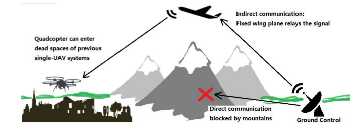
If your UAV does a mission in areas where you cannot directly, does it mean you have to abort the mission? With traditional UAV systems, yes. But with radio communication relay, NO! With the help of radio communication relay, the UAV can fly into areas where direct radio communication with you is blocked.
This idea is illustrated in Fig.1. If radio communication is blocked by, say, a mountain, then the use of relay can easily help us get arround the obstacle. In addition, relay can also help extend the range of communication, so you can go further with a radio transceiver of smaller power.
System Architecture
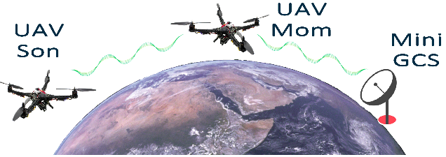
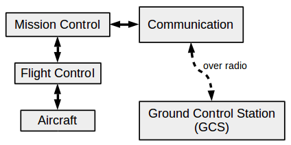
To demonstrate radio communication relay, a small UAV was constructed using 2 UAVs and a Ground Control Station, which we call “Mini GCS”. As shown in Fig.2, names are given to the UAVs: Mom is the one that relays communication at the middle, and Son is the one that actually executes the mission. Fig.3 shows the critical subsystems of the demonstration UAV system.
Communication
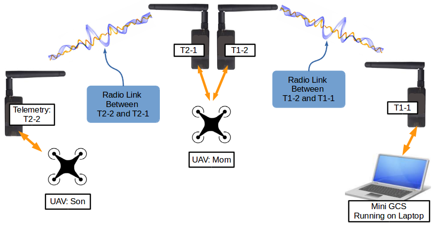
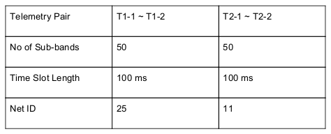
915MHz Radio telemetry by 3DR (3DR Radio) was used to construct the communication network. A total of 4 3DR Radios were used to establish 2 independent radio data links, one between Mom and GCS, and the other between Mom and Son (Fig.4). The 2 radio links are kept interference-free using the Frequency Hopping (FHSS) technique, which is a built-in feature of 3DR Radio. The 2 radio links use different frequency hopping sequence, which are determined by a unique “Net ID” (shown in Fig.5).

In order to detect errors in data transmission, a Cyclic Redundancy Checking (CRC) error checking stage was added. To do this, data is organized into frames, and the frames have fixed format (Fig.6). At then end of each frame, a 4-byte CRC code is attached. When a frame is received by UAV or GCS, the receiver will first record the CRC code received over radio (CRC_remote), and then compute a new CRC code based on the received data (CRC_local). If CRC_remote is equal to CRC_local, then the frame is error-free. Otherwise, the received frame has error(s) in it and has to be discarded. More details about CRC can be found here.
Mission Control
This mission control unit is used to do a number of jobs:
- It handles message routing and communication relay.
- It interfaces GCS to flight controller. User can send relatively simple commands from GCS, then mission control translates them into the low-level instructions to the flight controller.
- It is supposed to control the mission with intelligence, sadly we still haven’t implemented that (will we ?).
The mission control unit is in fact a software system, developed with ROS, than runs on a Raspberry Pi 2B. The mission control unit communicates with radio telemetries and flight controller through UART ports. So it means as long as you are using a UAV with supported flight controller (in our case, the PixHawk Flight Controller), then you can plug this mission control unit into it and turn it into an on-air communication relay station! The system is totally platform independent, which is cool and convenient.
Flight Control & Aircraft
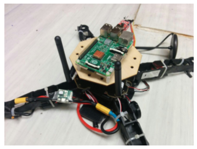
There is nothing very special with the actual aircraft used. For testing, we built 2 quad-rotor copters out of off-the-shelf components, and used them as Mom and Son. For flight controller, we selected PixHawk Flight Controller because it is powerful and plenty of resources are available online. Fig.8 shows the UAVs during a field flight test.

Ground Control Station (GCS)
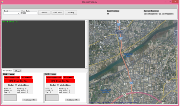
We developed our own version of GCS software, which we call “Mini GCS”. It was writen fully in-house using C#. A screen shoot is given in Fig.9 The Mini GCS has a number of cool features:
- A UAV status window, which allows you to monitor BOTH UAVs at the same time.
- A map display, that shows the location of both UAVs in real time.
- A Linux command line style interface, in which you can type commands and send them to the UAV that you specify, Mom or Son.
A number of useful commands:
arm              be ready to fly, engage motors
takeoff	         takeoff and fly to specified height
land             land immediately
setmode          change to flight mode of the UAV
rtl              return to home position, and land there
Testing and results
The video below shows how we tested the communication relay function. First, we let “Son” fly far enough so radio communication with GCS breaks (because radio telemetries are out of range). Then, we deploy “Mom” to serve as relay, after which radio communication of “Son” with GCS resumes. Communication status is indicated by the “Connected/Disconnected” icon in the bottom-right corner of the video, which turns Green when communication is healthy, and turns Red when communication breaks.
+
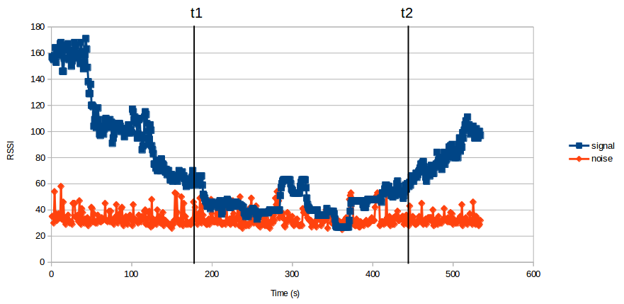
Fig.10 shows the variation of the radio’s signal and noise levels between “Son” and GCS during a typical mission (measurements not taken during the test shown in the video, but during a later test). As we can see, from t = 0 to t = t1, as “Son” started its mission and its distance to GCS increased, radio signal level dropped steadily. At t = t1, the radio signal level was almost equal to the noise level, implying a lost to radio communication. At this moment, “Mom” was started and deployed to the designated relay position (between “Son” and GCS). as “Mom” approached “Son” and the relay started to function, the signal level gradually rose again. At t = t2, signal level was above noise level, implying that radio communication between “Son” and GCS was re-established.

Leave a Comment