My First Home Made HiFi Audio Decoder and Amplifier
Recently I developed my first in-house hi-fi audio decoder + amplifier project. Having tested it with my own ears I was very much surprised by the outstanding sound quality. Considering the fact that this project has costed me less than 300 HKD (thanks to cheap PCBs from Shenzhen), I am sooooo happy with the result! It has a name: “JAudio Decoder Amp”
The Design
To realise this project with simple techniques and low budget, I selected a number of good-quality yet easy-to-use chips to base my design on.
I used PCM2707 computer interface chip + decoder + DAC. PCM2707 is a USB audio interface that enables music playback through USB. In addition to that it also has a built-in DAC that can convert 16-bit 44 kHz sound source with down to 0.006% THD into line. 16-bit 44kHz is standard CD-quality sound source, which I believe is the highest quality sound source that I can get most of the time. So I would not bother myself to use higher-quality DAC chips, which costs more and makes the design more complicated.
The built-in DAC of PCM 2707 can directly drive headphones with 32 ohm impedance, but the THD would be higher this way. Wanting to further improve sound quality, I used TPA6120 audio amplifier as output buffer. The amplifier is supplied with +5V ~ -5V, and the gain is set to 1.5V/V.
To generate the -5V required to drive TPA6120, a switch mode voltage converter, LM2594, was employeed to convert +5V (from USB Vbus) to -5V.
All 3 devices come from IT. Check data sheets for details and application information.
The complete and most updated schematic is shown in Fig.1, alone with some layout considerations.

The PCB
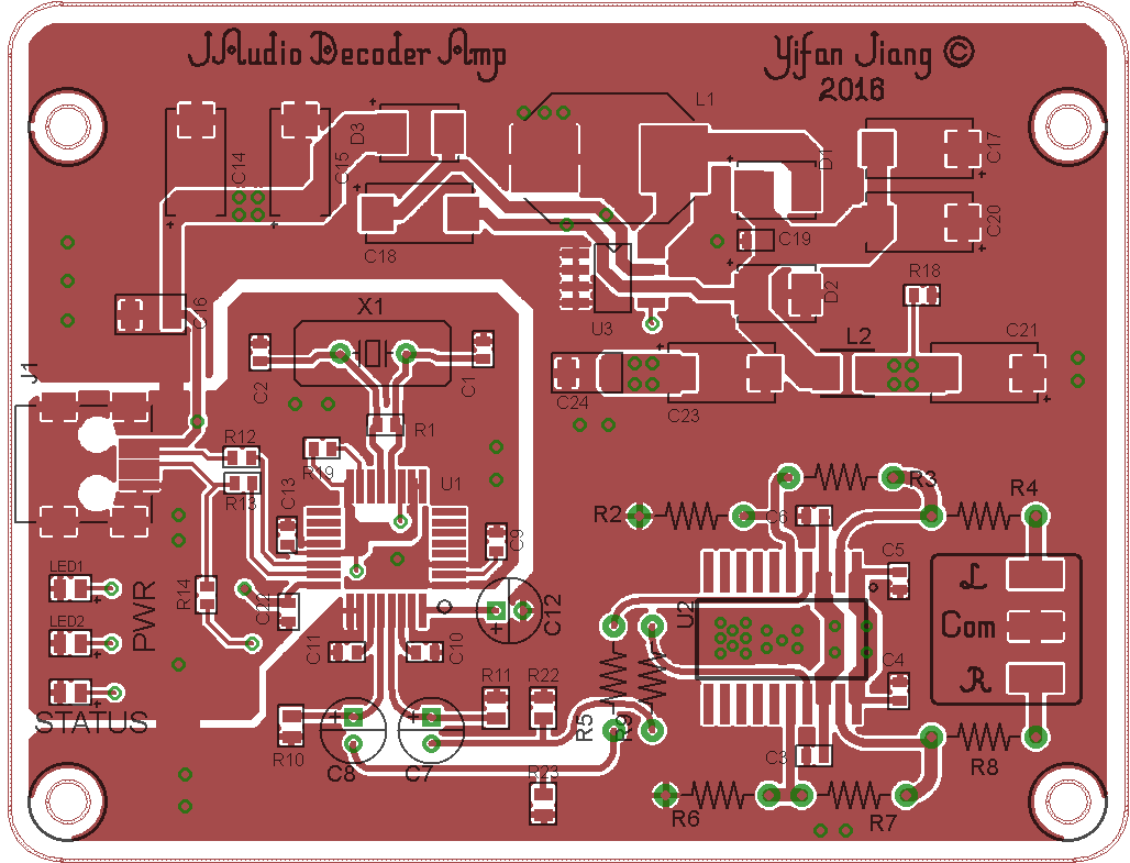
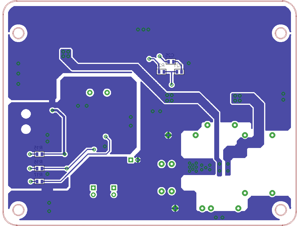
The PCB layout was created based on the schematic in Fig.1. It’s a 2-layer PCB, and it features separated ground panels for digital and analog circuitries, which helps reduce cross-over noise. According to the data sheet of TPA60120, for stable operation and optimum performance, there should be no ground panel underneath the output and feed-back pins of the IC. This recommendation was very well implemented. In addition, the output and feed-back paths were made as short as possible.
The design of the PCB is shown in Fig.2 and Fig.3.
The Final Product
After a few hours of assembly and some hardware debugging, my computer finally successfully recognized the chip, and sound flowed out like water. It has a crystal clear high-frequency, and rich mid-frequency, and decent low-frequency. The response is quite flat, being totally loyal to the original recording. When the music is off, there is no noise what so ever. I made a 5-minute comparison between my laptop’s audio output and this decoder. There is subtle differences, and the later offers clearer sound. From first impression I like my decoder better.
I used my Beyerdynamics DT880 headphone (32ohm version) for the above testings.
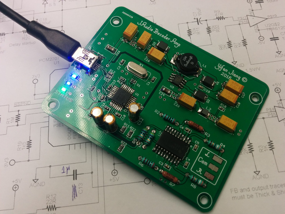
Haven’t washed the PCB yet, still covered with flux. But here is the final product (Fig.4 and 5).

There are minor problems with the board. First, sometimes my computer fails to recognize PCM2707, because of power supply instability at power-up. PCM2707 is supplied with 5V USB bus voltage, and its internal voltage regulator generates the 3.3V voltage needed for its internal operations. The internal voltage regulator, however, occasionally exhibits instability at power-up, causing the device to malfunction. The cause of the instability is the inadequate value of decoupling capacitor. I added as much as I could, and the device could function normally 90% of the time. Second, the power and status indicator LEDs have different brightnesses, which is kind of annoying.
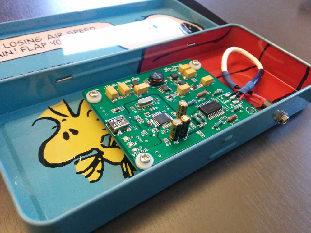
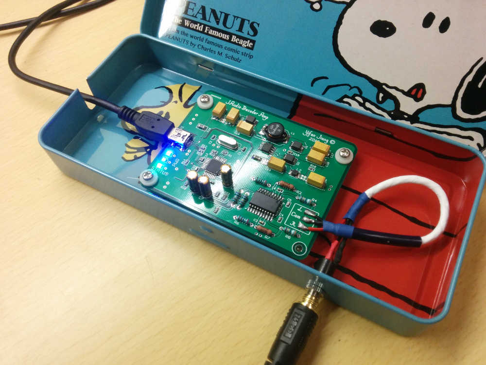
I made a cute little case for my decoder and amplifier, using a Snoopy pencil case. Look very nice, feel better to the touch!

Leave a Comment